Picture This...
Much time, effort, and care have gone into installing a water line. Crews have worked through inclement weather. Unexpected rock was found, slowing progress but not stopping the installation of the pipe. Crews have worked long hours to meet deadlines and are anticipating the end of the project.
But wait, you have not pressurized the line. All eyes are on that gauge, hoping to validate that the work was successfully completed.
The design engineer and owner anticipate news of a tight line ready to serve hundreds or thousands of customers or provide water to a new facility where many neighbors may find employment.
The following blog is a blueprint that, if followed, will lead to the successful hydrostatic testing of a water line using ductile iron pipe. The same basic principles can be applied to most other materials as well.
Hydrostatic Testing During Pipeline Design
Hydrotesting a new water line essentially begins during the design phase. Understanding testing factors during design will enable the water professional to prepare for obstacles that may arise during the testing process.
Test requirements are set by considering the following:
- Flow/volume demands
- Size and length of pipe
- Total overall difference from the low to highest elevations
- Changes in elevation or "high spots."
The hydrostatic test parameters must be clearly defined during the design phase and stated in the project specifications. Guidelines outlined in the AWWA M41 Manual and the ANSI/AWWA C600 Standard are as follows:
"Test pressure shall be 1.25 times the operating pressure. The duration of the test is two hours. Special consideration must also be given when multiple piping products are used."
A test pressure of 300 psi will be detrimental to weak materials, such as polyvinyl chloride (PVC) rated at 125 psi, which also does not have a safety factor of 2 and surge allowance of 100 psi included in the design, compared to the stronger Ductile iron that does.
Any material not designed for the specific pressures should not be used and should be isolated from any section of a line to be tested at higher pressures.
Education & Training Offered
Complimentary on-site training services are provided upon request by McWane Ductile product engineers or sales representatives to ensure installation crews are empowered with the knowledge to complete the process. Engineering professionals often include on-site training by the manufacturer in the project specification to ensure training is completed.
There is also a benefit to documented standards compared to word-of-mouth training. How many times in your life have you encountered a situation such as this one: A newlywed wants to cook Thanksgiving dinner. Her husband does not understand why she is cooking a 5-pound turkey in a 10-pound pot. The bride responds, "That's the way mom did it." The husband then asks his favorite mother-in-law the same question and receives the same response, "That's the way my mom did it." The husband then presents the question to Grandma. Her response was, "That was the only pot I had!"
We may chuckle a little, but this happens all too frequently in the field. A better solution is to base training on documented resources such as the AWWA M41 Manual or the ANSI/AWWA C600 Installation Guide for Ductile-Iron Mains and Their Appurtenances.
Installation of the Ductile Iron Pipeline
Attention to detail is of the utmost importance:
- Cleaning the bells, spigots, and gaskets
- Proper lubrication of gaskets and spigots
- Use of approved accessories
- Mechanical Joint installation should include gasket lubrication, straight alignment, and specified bolt torque.
- Proper alignment of joints during the homing process - "Straight is great!"
- Deflection of joints -after the pipe is homed
Anyone who has searched for a leak will attest to the importance of proper installation. Regardless of the pipe material, improper tightening/torque of MJ bolts is extremely likely to be the most common installation issue.
Hydrostatic Testing of Your Ductile Iron Pipeline
ANSI/AWWA C600 Installation Guide for Ductile-Iron Mains and Their Appurtenances.
WARNING: The testing methods described in this section are for water-pressure testing only. These procedures should not be applied for air-pressure testing because of the serious safety hazards involved with compressed air. Also, pipelines intended for buried service should generally be tested with the backfill in place.
Steps to Follow During Hydrostatic Testing
- Slow fill the line. This will enhance the probability of removing aII air from the conduit.
- Fill the line at the lowest possible location while providing an air release at the highest location. Due to the contour of the line, multiple air release locations may be provided.
- Practice patience. It is beneficial to allow all the air to vent and adequate time for any water absorption in the cement lining.
- The test pump is to be connected at the lowest point of the line.
- Prime the pump to remove all air prior to engagement with the line.
- The pressure gauge is to be connected to the pipe at the lowest location. *Reminder: Connect the gauge to the pipe, not the pump.
- The pump should be isolated from the line during the actual test period.
- All head pressure will thus be included in the reading on the gauge.
- It is important to isolate the new line for pressure testing, allow it to be properly chlorinated, and test it for bacteria prior to connection with a service line.
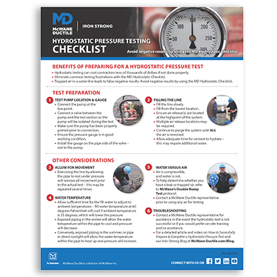
With this free Hydrostatic Pressure Test Preparation Checklist from McWane Ductile, you can avoid negative test results and succeed the first time!
Allow for Movement of the Water Line
When pressures are increased or decreased, a water line moves like an accordion. The trench type specified for the project is intended to balance the external forces involved but will not eliminate movement. Therefore, the number of times a line is exercised may vary. Installers may, at times, have a misconception that water lines do not move because of earth loads of six to eight feet, for example.
Water Temperature Considerations
Water temperature is not typically a huge factor during hydrostatic testing but must be considered. Internal pressure will decrease as water temperatures decrease- to the point where the fluid begins to freeze, which then creates a substantial issue.
Alternatively, pressure will rise as water temperature increases. If a water line installed in the winter is filled with city water at 60 degrees Fahrenheit and the ground temperature is 32 degrees Fahrenheit, the water will cool, and the pressure will drop.
Conversely, the internal pressure may increase for an above-ground line installed during summer months when the water is 60 degrees Fahrenheit and the ambient temperature is 90 degrees. This is especially true if the line is exposed to direct sunlight.
Pressure Versus Make-Up
A common mistake is for installers to chase a leak for extended periods of time, only to find the line will eventually pass the hydrostatic test without changing any parts of the water line. Allowable make-up water may alleviate this issue.
Table 4-A, found in section five of the ANSI/AWWA C600 Standard, identifies the amount of make-up water used (per hour) to increase the pressure back to the starting point of the test. The same information may also be obtained in seconds via the McWane Ductile Pocket Engineer.
McWane Ductile Tools
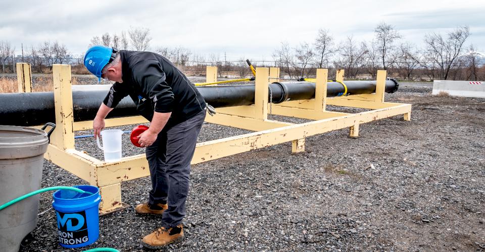
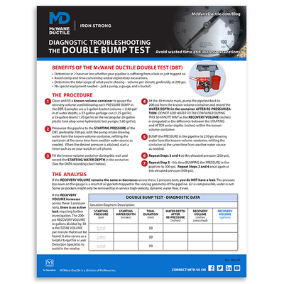
The McWane Ductile Hydrostatic Diagnostic Protocol, also known as the Double Bump Test," is an excellent diagnostic process written for operators to differentiate a leak from trapped air:
- Three hydro tests are conducted, each with the same time intervals.
- The pressure is increased during each test.
- The make-up water is measured and documented after each test.
- Ensure the pump is primed before the valve is opened to the water line.
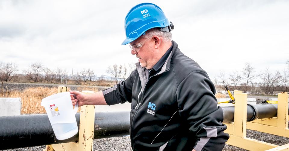
- The water supply container must be marked at the water level to assist with calculating the make-up water.
- A "known value" container such as a quart jar or incremented gallon bucket may be used to refill the original supply source.
- The amount of make-up water is documented and compared from all three tests.
RESULTS:
If the amount of make-up water remains the same or slightly improves, this is an indicates trapped air. A substantial increase in the amount of make-up water as the pressure is increased indicates a leak is present.
Testing With Air
Let's be perfectly clear: An air test is absolutely not the same as a hydro test. Note the statement from the ANSI/AWWA C600 Installation Guide for Ductile-Iron Mains and Their Appurtenances:
Is it a leak or just trapped air? Be confident with your pressure test results by downloading and using this handy Double Bump Test Tip sheet!
Hydrostatic Testing
WARNING: The testing methods described in this section are for water-pressure testing only. These procedures should not be applied for air-pressure testing because of the serious safety hazards involved with compressed air. Also, pipelines intended for buried service should generally be tested with the backfill in place.
We recommend using hydrostatic test procedures for all water lines if possible. The dangers of compressed air cannot be over emphasized.
Think about it, you have installed a water line - test with water. If, as a last resort, testing with air is the only option, there are items of concern:
- Two to four psi is all that is required for an air test.
- The dial on the gauge must be in one psi increments.
- A pressure relief valve is to be set at five psi max to prevent over pressurizing.
An example to compare water and air: fill one balloon with water and the second with air. Pop both balloons. The water balloon will simply fall to the ground while pieces from the air balloon may travel several feet when popped.
Yes, a ductile iron cap is heavier than a balloon, which ultimately means it will do more damage when it lands. Work smart, work hard, and work safe!
Conclusion
Hydrostatic testing requires considerable thought, preparation, and attention to detail. Fortunately, there are documented procedures and knowledgeable McWane Ductile staff available for assistance. From design to installation, we take great pride in providing education and training to water professionals throughout the water and wastewater industry. Together, we are Building Iron Strong Utilities for Generations!
Need Assistance with Your Waterworks Project?
If you have any questions regarding your water or wastewater infrastructure project, your local McWane Ductile representative is equipped with the expertise to assist you. Many of our team members have managed small and large water utility systems, served in engineering consulting firms, and bring decades of experience solving field issues involving pipeline construction and operation. From design to submittal to installation, we strive to educate and assist water professionals throughout the water and wastewater industry.

