Within this #IronStrong Blog, we will discuss the depth of cover and the key factors to consider when selecting the type of trench (or laying condition) for your application. We’ll also discuss why it is important to choose the correct trench application, not only for today but also for future adjustments or improvements planned for the surrounding area where the pipeline is being installed.
What is Depth of Cover?
In the simplest terms, depth of cover refers to how deep the pipeline will be installed, or how much earth and backfill (typically in feet) will be placed on top of the pipeline to restore the surrounding land to its original, or newly projected elevation.
Ductile iron pipe is very conservatively designed, meaning it is typically stronger than its rating indicates. This is an “added benefit,” so to speak, in choosing Ductile iron pipe. But the selection of the pipe to be installed should still follow the design criteria for the specific diameter and wall thickness.
Some variables that often come into play when selecting the required wall thickness of the pipe are:
- Depth of Cover
- Trench Type
- Wheel and Surface Loads (lbs.)
- Internal Pressure
Because of its durability and strength, in almost all cases, Ductile iron pipe requires a much thinner wall thickness, very little depth of cover, and less stringent trench-type requirements compared to alternative materials. We suggest visiting the Calculators tab in the McWane Pocket Engineer app for more details on which pipe best meets your application's specific needs.
Why is the depth of cover so important in relation to selecting the correct wall thickness for the Ductile iron pipe in your application?
As mentioned above, the general design of Ductile iron pipe is very conservative, which essentially allows for very little earth to be placed on the pipe while still performing without failure.
That said, the deeper the pipeline is installed, the greater the weight and external loads on the pipe's outer wall due to the soil's weight. The shallower the pipe is installed, the more it will be exposed to potential damage from traffic above the installation. In most cases, selecting the correct wall thickness and trench type for the application should be sufficient to overcome these.
A depth of cover that is less than 2.5 feet is generally not recommended due to the potential damage that can occur to the pipe and/or the pavement above it. Depending on the depth of cover and/or the surface load, it is very possible that a thicker wall or more stringent trench type may be needed to prevent the pipeline from failing as a result of the external loads that it may experience once in service.
Examples of external loads and forces can include:
- the weight of the backfill
- motorized traffic (pipelines under heavily traveled roadways, railroads, etc.)
- buildings and structures
- or other unique scenarios related to the specific application and laying conditions.
In conjunction with selecting the appropriate pipe wall thickness for the pipeline's burial depth, we will also consider the appropriate trench type. We’ll also discuss trench types and what their role is in the proper installation of ductile iron pipe later in this blog.
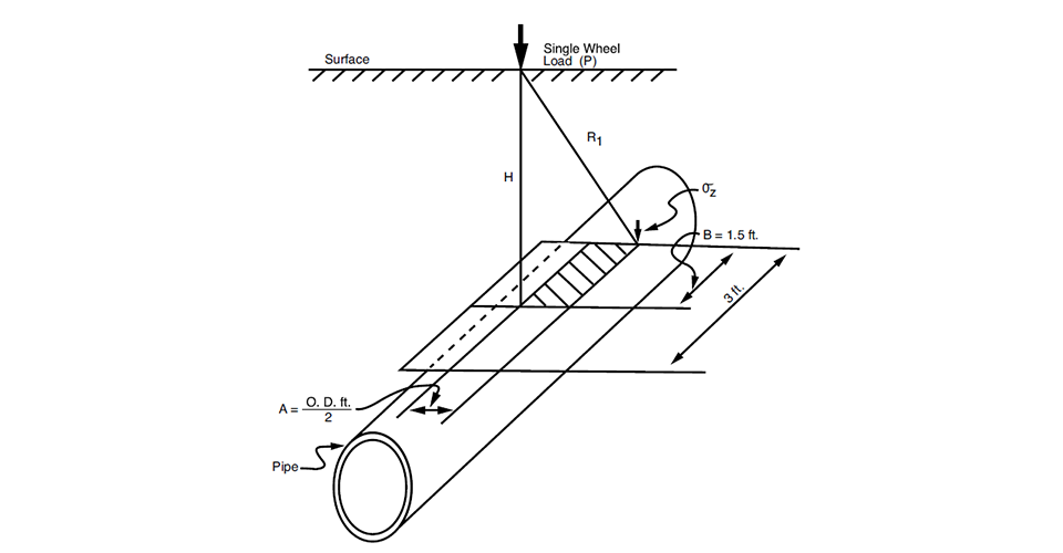
When examining the surface load factor, a calculation is performed to predict how the wheel load (the weight of an object, typically a vehicle) at the surface is transmitted and distributed through the soil to the pipeline.
Without getting into the complex details of the equation, it essentially predicts how the load's weight will be distributed over a 3-foot section of the buried pipeline.
Various parts of the equation take these factors into account:
- depth of cover (ft.)
- outside radius of the pipe (ft.)
- vertical stress (psi)
- point load at surface (lbs.)
- depth in inches
- distance from the point load.
The diagram below is a good visual aid that shows exactly what the equation calculates.
In conclusion to this section, it is important to select the proper wall thickness for the pipeline -- one that can withstand both the depth at which it is buried and the external wheel (or surface) loads it will be subjected to once installed.
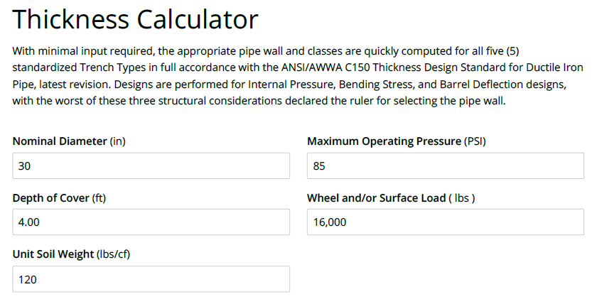
You can easily see which wall thickness is required for your specific depth of cover (along with the required Trench Type) by entering a few variables within the McWane PE Thickness Calculator.
What are trench types, and how do they relate to the proper selection and installation of Ductile iron pipe?
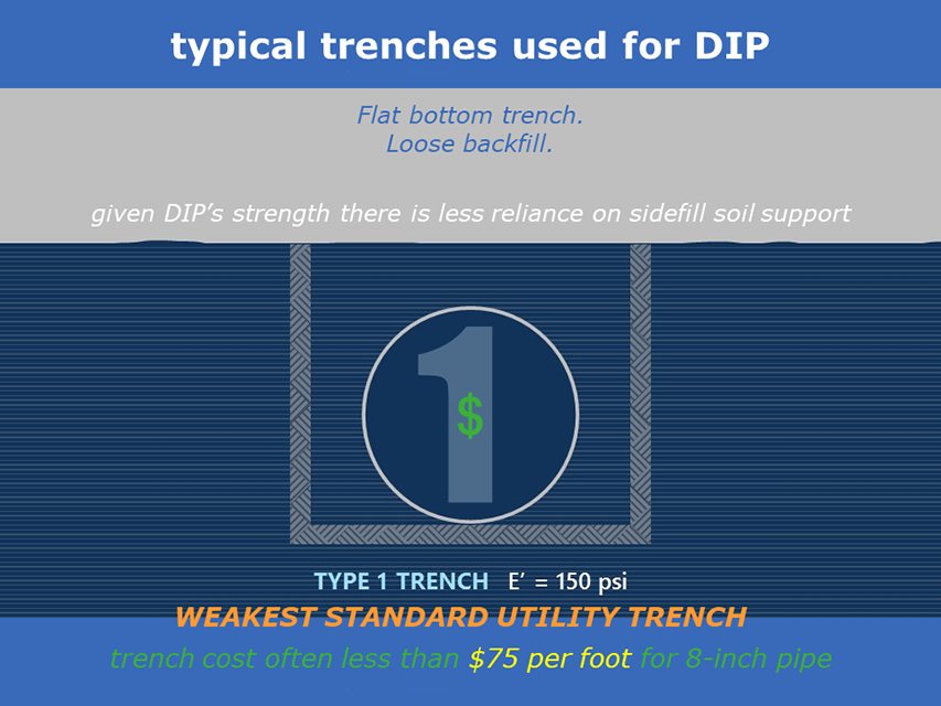
Trench types are standardized descriptions of how the trench where the pipe will be laid is constructed. There are five types of trenches as described below.
Type 1
A typical Type 1 trench is a flat-bottom trench with loose backfill. “Flat-bottom” is defined as undisturbed earth. For 14-inch and larger pipes, consideration should be given to using laying conditions other than Type 1.
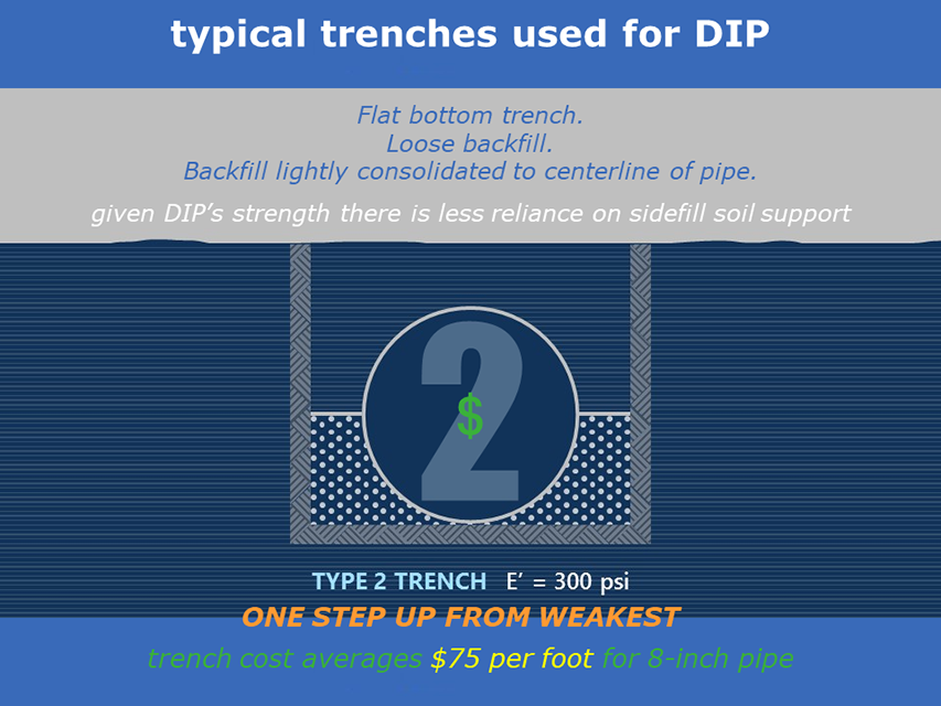
Type 2
A typical Type 2 trench is a Flat-bottom trench, backfilled lightly consolidated to the centerline of the pipe. “Flat-bottom” is defined as undisturbed earth.
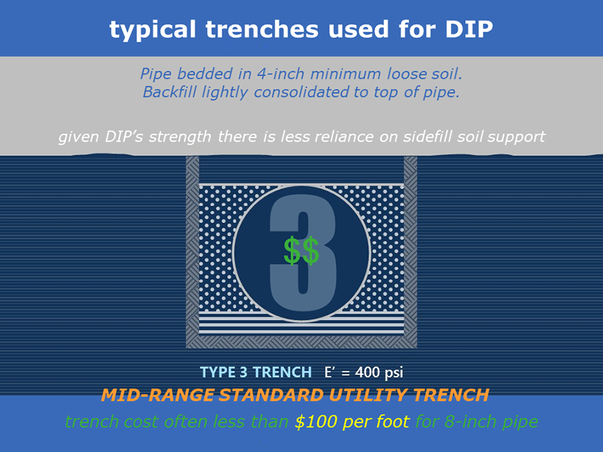
Type 3
A typical Type 3 trench is the pipe bedded in 4 inches (minimum) of loose soil, backfilled lightly consolidated to the top of the pipe. “Loose soil” or “select material” is defined as native soil excavated from the trench, free of rocks, foreign materials, and frozen earth. Type 3 trenches are typical in the installation of Ductile iron pipe, as they are most closely related to what you would typically see when digging up and re-using the native earth as backfill material.
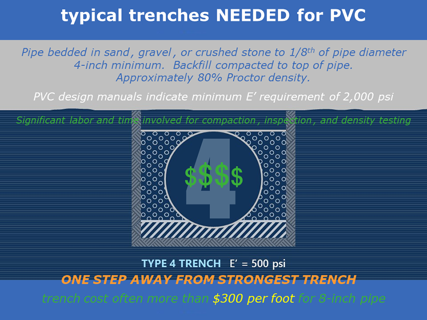
Type 4
A typical Type 4 trench is pipe bedded in sand, gravel, or crushed stone to depth of 1/8 pipe diameter, 4 inch (minimum). Backfill compacted to top of pipe. (Approximately 80 percent Standard Proctor, AASHTO T-99)
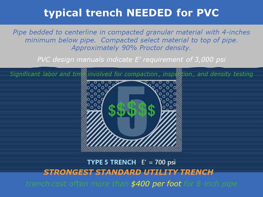
Type 5
A typical Type 5 trench is pipe bedded in compacted granular material to the centerline of the pipe. Compacted granular or select material to the top of the pipe. (Approximately 90 percent Standard Proctor, AASHTO T-99). “Loose soil” or “select material” is defined as native soil excavated from the trench, free of rocks, foreign materials, and frozen earth.
Why is nominal thickness (wall thickness) important?
As a by-product of the inherent strength of Ductile iron pipe, it is very capable of being laid in any of the trench types shown. With the noted exception that 14-inch and larger pipe should only be used in a trench type other than Type 1.
As we have discussed, the chart below shows that the nominal thickness (wall thickness) required for your application typically increases with the depth at which the pipe is to be laid. Along with this increase, you will also notice that the maximum depth of cover will also increase as you move from a Type 1 trench up through a Type 5 trench for each respective nominal thickness.
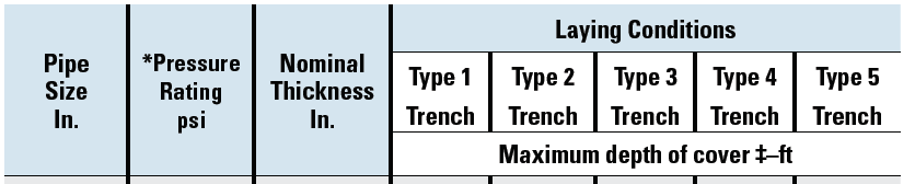
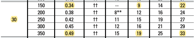
Example:
Using 30” as our example, you will see in the chart that it can be installed with a maximum cover depth of 9 ft using a wall thickness of 0.34” and a Type 3 trench.
The same 30” (wall thickness .34”) can also be installed with a maximum cover depth of 22 ft if the trench is constructed as a Type 5.
By upsizing the 30” wall thickness from .34” to .49”, it can be buried at a maximum depth of cover of 19 ft in a Type 3 trench, or 33 ft if being used with a Type 5 trench.
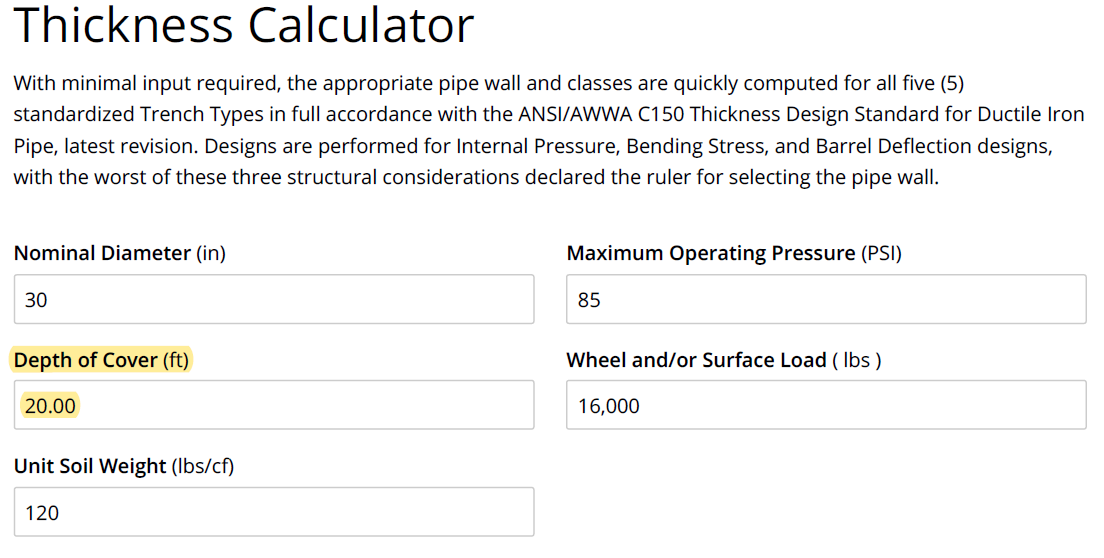
Let’s look at an example of how depth of cover and trench types can factor into your project.
For this example, let’s utilize the McWane Pocket Engineer calculators and look at an installation of 30-inch Ductile iron pipe. For the sake of discussion, we will say the project was designed to use a CL 150 pipe buried at a 4-foot cover with a Type 3 trench. As you can see from the chart below, this was the correct selection of wall thickness and trench type for the application.
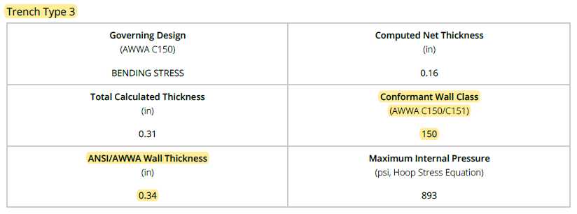
Under normal circumstances, the selection of a 30-inch CL 150 utilizing Trench Type 3 meets all necessary installation criteria and is properly designed. But what would happen if, after the pipe was manufactured and during construction, it were learned that a future project would alter the elevation of the land directly above the installed pipeline, raising it by 16 feet once the roadwork was completed? Essentially, the pipeline, buried with 4 feet of cover, would be fine as installed at least until an additional 16 feet of elevation is added to the surrounding area, based on today's assessment.
The above may or may not be a concern of yours, but if you find yourself in this or a similar position, there are some alternatives to explore.
Although it may not be a concern at this time, there is potential in the future to require relocation or replacement to meet the new criteria. As you will see in the next chart, changing the depth of cover from 4 feet to 20 feet (existing 4 feet of cover + an additional 16 feet of cover) changes the required thickness class and/or trench type for the pipe. As we discussed earlier, the deeper the pipeline is laid, the greater the required wall thickness, unless a more stringent trench requirement is used.
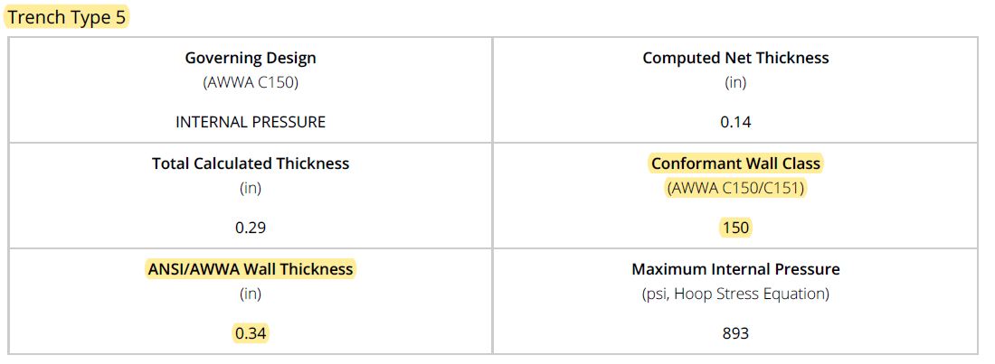
As shown in the calculations, there are three options to address this situation, if you choose. The options below would incur various expenses and require negotiations with the engineer of record and the project owner prior to moving forward.
Option #1 – Replace pipe, use the same Type 3 Trench
Once negotiations are complete and a decision is made to adjust the current work to accommodate a future adjustment, you can replace the CL 150 pipe with the CL 53 pipe and continue using the same Type 3 trench.
With this option, keep in mind that the replacement pipe will cost more than the original (due to the required thickness), and you will lose production while you wait for the pipe to be manufactured, delivered, and installed. All of which become issues that need to be negotiated with the engineer of record and owner of the project.
Option #2 – Use CL 150 pipe, use Type 5 Trench
To accommodate the proposed future work, you can continue to use the CL 150 pipe on site, but you would need to move away from the Type 3 trench and begin installing the pipe in a Type 5 trench.
Again, this option would need to be negotiated with the engineer of record and the project owner, but it would limit costs and downtime if it were decided that the future work needed to be addressed during construction of the current project.
Option #3 – Do nothing
Your final option would be to do nothing. Simply continue installing the pipeline as designed based on today’s assessment of the project. In most cases, you will find yourself obligated only to install the pipeline as designed.
If the engineer of record and owner are aware of potential conflicts that may arise from future work and decide to proceed as planned, that is fine, as the current installation from our example meets all the requirements for a 30-inch CL 150 pipe to be installed at a depth of 4 feet using a Type 3 trench.
Conclusion
Although depth of cover and trench type may not always be considered important factors when installing Ductile iron pipe, they play a vital role in selecting the proper wall thickness for your pipe.
As we wrap up this discussion regarding depth of cover and trench type, we’d like to remind you to please contact your local McWane Ductile representative. We go far beyond just manufacturing Ductile iron pipe, and we would be happy to assist with any questions you may have. We also offer on-site classroom or job-site training for you and your crews.
Check out all our digital offerings: